4.8 Extras
4.8.1 Stereo
Activates the stereo-view. The preset is anaglyphic view, in this case you will need red-cyan-glasses
(or red-green, though red-cyan will give better results).
It is difficult to actually work in stereo, as the mousepointer itself is not an object
in the 3D-scene. Thus the stereo-view is meant rather for viewing than for creating a
scene.
4.8.2 Stereo-mode
-
Anaglyphic view
- The scene is split into two scenes using red and cyan.
-
Quad-Buffer:
- For quadro-cards that support stereo in hardware.
-
Separated horizontally:
- The two images for the two eyes are displayed beneath each other
on the screen.
-
Separated vertically:
- The two images appear above each other on the screen.
4.8.3 Projection
Here you can switch between parallel and central projection (the default). In both modes the
option ’2d’ can also be chosen. In this mode, the view will be normalized onto the xy-plane. In
combination with parallel-projection, the 2d-mode is like using a 2d dynamic geometry
software.
In case you would like to use the coordinate-system but hide the z-axis you can set the values
zMax and zMin to 100 in the ’extras - settings - sizes’ dialogue. When changing to 2D-mode you
will be asked if this setting should be applied automatically.
4.8.4 Import / Export
-
Write construction as graph:
- Writes the construction in VCG-format. You can display
this file with VCG-Graph, the graph shows in which way the objects depend on
each other. See http://rw4.cs.uni-sb.de/users/sander/html/gsvcg1.html for
an explanation and download.
-
CAS Export
- Writes the constructions to a textfile which is readable for computer algebra
systems. At the time being no working import-routines exist on the CAS-side.
-
Construction description:
- As the name suggests this menu gives you a complete
description of the current construction.
-
Construction protocol:
- This gives a complete protocol on how the construction was made.
Here - in contrast to the construction description - deletions and undos are visible,
too. For each action a timestamp is included, which makes this function valuable for
teachers and researchers.
-
Import mathematica polygons:
- Imports polygon-objects from Mathematica-files.
-
Approximate locus surface through polynomial:
- For a given locus surface this
computes a polynomial to fit the surface. You will have to enter the degree of the
polynomial first. In case the achieved exactness is less than 10-6 one can assume that
the surface really is of the given degree.
While this function can be called for locus-lines, too, the results are nonsensical. If you
have a curve in the xy-plane and want to compute its equation you can construct the
normal through the point on the curve to the xy-plane, trace this normal to get a locus
surface and compute the equation of this surface.
4.8.5 Optimize
This function optimizes the scenes representation internally. As this can lead to problems when
continuing to work on the scene you should save befor optimizing.
This function is only useful for very large constructions that cannot be rotated fluently
anymore.
4.8.6 Slider
Generates a new slider. Sliders have the following features:
- Sliders are expression of the type ’number’. The value of a slider can be used in other
expressions.
- At the same time sliders are objects of type ’point on line’ and can be used to drive a
locus.
- Sliders are displayed independently of the rotation of the scene.
Thus sliders are ideally suited for adjusting parameters.
In the sliders context-menu you can edit the possible values of the slider. If the slider drives a
locus, the domain of the locus can be automatically adjusted to the range of the slider. Choose
’automatically adjust to circle or slider’ in the locus’ properties-dialog. Thus it is very easy to edit
the domain of a heightfield if you construct it using a slider.
Example: Choose ’Typical tasks - co-ordinate axes’. Generate two sliders and name them x and
y. Enter an expression e1*x+e2*y+e3*(x*y). Generate a point from this expression and then
select x, y and the generated point. Press Alt-o. You get the graph of the heightfield
z = x ⋅ y.
Check ’automatically adjust to circles and sliders’ for x and y in the locus’ properties-dialogue.
In case you change the range of one of the sliders the locus will change in real time.
4.8.7 Light
Generates a light-object in the origin. Besides being a light, this object behaves like a point: It can
be moved, used in animations and be attached to objects.
4.8.8 Shadow
To create a shadow, select a light, arbitrary other objects and the object the shadow should be cast
on as the last object. Pressing ’shadow’ then generates a projective shadow.
4.8.9 Activate shadows globally
This command activates a shadowing-algorithm for the whole scene. It works best under windows
where I implemented a workaround against self-shadowing artifacts. Choose ’ShadowMap’ as your
shadowing algorithm.
To turn of the global shadows you will have to restart the program.
4.8.10 New Animation
A point and a two-dimensional object (line, segment, circle) must be selected. After selecting the
menu a dialogue appears that lets you adjust the start- and endpoint of the animation and the step
size.
You can get the start- and endpoint by adjusting the point in the construction and then
pressing the button ’Get value from construction’.
4.8.11 Start / stop animations
Starts or stops all animations defined in the construction, see ’New animation’, too.
4.8.12 Fly around
Opens the current construction (without co-ordinate system) in an external viewer. Here you can
fly around in the construction in fullscreen. Press ’h’ for help. The viewer is part of the
OpenSceneGraph-library, see http://www.openscenegraph.org.
4.8.13 Convert hidden objects to auxiliary objects
By selecting this menu all hidden objects are redefined to be auxiliary objects. This is useful
for macros where the object-tree should not be bloated with objects when using the
macro.
4.8.14 Group objects
A group-object containing the selected objects is generated. This will give you the following
possibilities:
- You can select the group as a whole.
- You can deselect the group as a whole.
- The group is an ’arbitrary object’ that can be intersected with planes and lines. To
examine the intersection of a polyeder with a plane, you will have to group the sides of
the polyeder and then intersect the group with a plane.
- To select a member of a group as a single object, you will have to press ’TAB’. The
single object appears behind the group.
- When deleting the group the members are ’freed’, not deleted.
- In the treeview the objects of a group appear as subitems to the treeitem of the group.
This way you can organize your tree-structure.
- Groups can be intersected with other objects (including groups) using the
intersect-button in the smaller toolbar. This way all intersections with all members of
the group are calculated. Be aware that possibly very many objects will be constructed!
- Groups can be nested. See the macro ’free cube’, that can be found in ’Macros - Platonic
solids’ for an example.
4.8.15 Make selected objects blink
If you check this item, the currently selected objects will blink. While this can be useful in
fullscreen-mode, I personally do not like this setting.
When constructing an object with ’New object’, this mode is automatically selected
temporarily.
4.8.16 Lock selected objects into position
When dealing with non-dynamic constructions it can be desirable to lock basepoints into position.
This command does this for all selected points. All selected objects that are not points will be
ignored.
Note that locking into position has an effect only for free points. Constructed or half-free points
will still bepositioned depending on their parents.
4.8.17 Choose language
As the name says. Changes will take effect after restarting the program. The default is the
language of the underlying operating system. At the time being only German and English
are available. The program itself (excluding the documentation) has been translated to
French and Traditional Chinese, too. The chinese version will work on a chinese windows
only.
4.8.18 Settings
Here various settings for Archimedes Geo3D can be adjusted. These are saved together
with the construction. If you want those settings to be used as presets, press ’Use as
preset’.
-
Paths:
- The paths for file-actions can be set here. It makes sense to have separate directories
for models, textures and constructions, which can be set here.
While running Archimedes the directory that was used last will be taken as the current
setting. If you want those directorys to function as presets, press ’use as preset’.
-
Colors:
- You can enter colors for all objects that will be used when constructing a new object
of that type. A color consists of four values: The values for red, green and blue and
the alpha-value. Alpha = 0 means that the object is completely transparent (and thus
invisible, but still pickable), apha = 1 gives a completely solid object.
-
Sizes:
- A size for all objects can be entered which will be used when constructing new objects.
For linear objects (lines, segments, vectors, circles and locus-lines) this is the thickness
of the objects. For planes this number determines how big a part of the (infinite) plane
should be displayed. Possible values are floating-point numbers between 0 and infinity.
The values xMin, xMax, yMin, yMax, zMin and zMax specify the range of the
co-ordinate system.
-
View:
- Settings for the appearance of Archimedes Geo3D.
-
Show co-ordinate system:
- If checked, the xyz-co-ordinate system will be shown.
-
Show list:
- If checked, the list containing all objects names (that can be used to select
objects, too) will be visible.
Since version 1.1, the object-list has been hidden by default, as it has been replaced
by the object-tree. In case you rather want to work with the object-list (because
you are used to it, for instance), you can show it here (or hide it when it shows
up in a construction that was made with an older version).
-
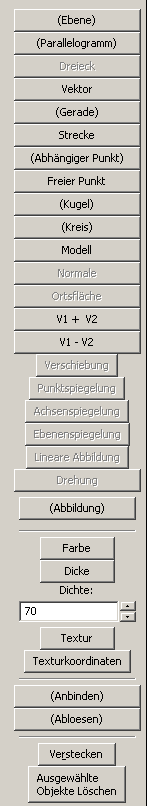
Show buttons:
-
The buttons stem from the very beginning of Archiemedes Geo3D:
Here all constructions can be selected. Note that you get even more information from the
buttons than from the symbols: If two lines are selected, the button ’point’ changes to
’intersection-point of two lines’.
In practice the buttons proved to be hard to find because of the abundance of text, thus
the toolbar with the symbols.
The buttons ’Color’ and ’Thickness’ are useful if you want to change more than one
object at once. Select the objects and then press ’Color’ or change the value of
’Thickness’.
-
Show point labels:
- This setting controls if labels for points should be shown or
not.
-
Background color:
- Here you can set the background-color of the screen.
-
Reset:
- Resets all values to the ones that were used after the installation of Archimedes. If you
press ’Use as preset’, too, these settings will be used as presets.